CAD-CAM and Hermle.
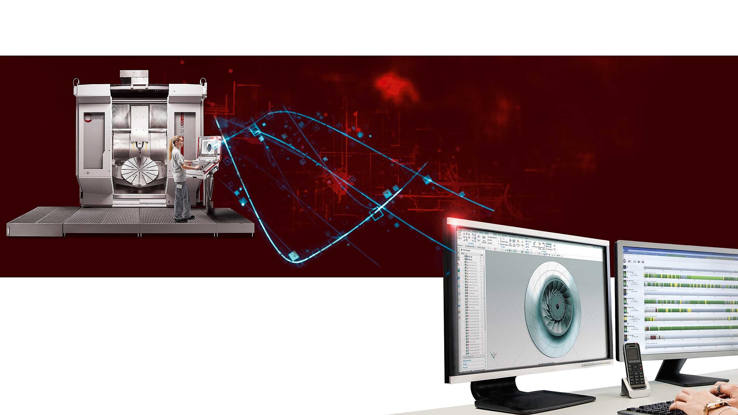
What is CAD/CAM? They are the brain and hands in a manufacturing process.
CNC-controlled machining centres are highly complex masterpieces of engineering.CNC may be quickly jotted down,but the technology behind it is highly sophisticated –orrather the multitude of technologies and the variety of different software variants, in particular of software applications that fall under the umbrella termsCAD andCAM.These software applications have become indispensable in most areas of the mechanical engineering industry.
This is also, and particularly, the case at Hermle,where CAD-CAM systems have long been a key component of the integrative manufacturing process.
But what is CAD/CAM? And what exactly do these two systems allow us to do?How are they interconnected?And what is it that makes them so indispensable?Below you will find an overview of the two applications.What they stand for and what they can do.Firstly, CADstands for Computer-AidedDesignand CAM stands forComputer-AidedManufacturing.To put it simply, CAD and CAM can be described as the brain and hands in a CNC-controlled manufacturing process.CNC, on the other hand, stands forComputerNumerical Control (if you would like to know more aboutCNCand its applications, please click on thelinks provided in the text).CAD/CAMshould be distinguished fromCAE, which stands forComputer-AidedEngineering.Here, too, there is a wide range of connecting factors, but for the purposes of this overview we will be focussing onCAD/CAM systems –which we will now examine in turn. CAD will be discussed first, then CAM,and finally the wide range of software variants that link the two applications with one another.
CAD–a program for the design phase.
CAD systemsdo not just play a key role in mechanical engineering,but also in numerous other sectors and branches of industry, e.g. in architecture, the automotive industry,aerospace,electronic design and in many other areas– from design through to production. In short, benefits include an acceleration of the design process, a minimisation of potential errors and improvements in efficiency overall.Computer-Aided Design is used to help create, modify and analyse digital models and drawings of objects or products.For precisely these reasons, architects, engineers, designers and otherprofessionals use the software application for their respective2D and3D models.Their work is far from trivial and it is really worth taking a closer look at how the program works.Generally speaking, the program can be used to design anything.
The primary functions of a CAD system include:
- Creation of geometry:CADallows users to create precise 2D and3D models of objects.This can be done by drawing lines,circles, arcs and other geometric shapes.This geometry can then be edited and modified.
- Modelling:Modelling goes beyond the drawing of lines, circles and other shapes.CAD systems offer tools and features for the creation of surfaces,solid bodies, free-form surfaces and other shapes that enable a realisticrepresentation of objects.
- Editing and modification:CADallows users to edit and modify models by adding, deleting or changing elements. This means that design changes can be implemented quickly and efficiently.
- Size accuracy andprecision:CAD systems offer precisemeasures and sizing functions to ensure that models are in line with the desired standards and specifications.Distances, angles, radii and other dimensions can be precisely defined and compliance can be checked at any time.
- Visualisation:CAD enables models to be shown in various views, includingwire frame models, surface models and photorealistic renderings.This helps to illustrate the appearance and behaviour of the final product.
- Analysis and simulation:CAD systems can also offer capabilities for performing tests, analyses and simulations.These include, for example, structural analyses, movement simulationsor flow simulations to examine the behaviour of products under various conditions.
CAM–used by programmers to control machines and speed up the manufacturing process.
WhileCAD creates the models to be fabricated,CAM, orComputer-AidedManufacturing, refers to the use of computer software to control machines and tools in manufacturing.In other words, the programmers of CAM systems use the information in CAD models to automate the manufacturing process.They generate tool paths and instructions for CNC machines and other manufacturing systems.This enables the precise fabrication of products in accordance with the specific design specifications defined in the CAD models.In other words, the CAM system “hitches on” to the CAD system andthe two systems are fully interlinked within the CNC machine.Here too, it is worth taking a look at the details.
ACAM system is a software application that supports the manufacturing process by providing computer-aided tool paths and instructions for machines.A CAM system reads the data from CAD models and converts it into machine-readable instructions to enable the production of physical products.In milling, for instance, this includes work steps such as5-axis roughing,adaptive roughing, pre-finishing,finishing or engraving.It is thus a complex interaction of fine and ultra-fine movements that remove varying amounts of material – sometimes large amounts and sometimes small – at different speeds.However, the amount is always the exact amount that has been requested and entered.An example of this can be found here.
When examined in detail, the primary functions of a CAM system are as follows:
- Tool path generation:TheCAM system automatically generates tool paths on the basis of geometric informationfrom the CAD model.It calculates the optimum movement of the tool along the surface of the workpiece, thus enabling precise and efficient machining. The CAM data required for this provides details such as start and end points for the tool movement, traverse paths, milling or turning movements and other parameters required for machining.
- Tool selection:The CAM system assists in the selection of suitable tools for the manufacturing process.It takes into account factors such as the type of material, the desired surface quality and the level of accuracy required to select the right tools for the machining task.Accordingly, the CAM data contains information on parameters such as tool diameter, tool length, tool type (mill, drill, turning tool, etc.) and other tool attributes required for correct machining.
- Machining strategies:CAM systems offer various methods to maximise the efficiency of manufacturing.These include milling, turning, drilling, cutting and other machining techniques.The CAM system determines the optimum machining strategies on the basis of the specific requirements of the design and the selected machine configuration.The CAM data specifies the speeds at which the tool should physically move during machining.This includes, for example, the movement speed of the tool relative to the workpiece, the so-called feed rate, as well as the cutting speeds, i.e. the speed at which the tool cuts the material.
- Collision detection: The CAM system performs automatic checks to identify potential collisions between the tool, the workpiece or other components during the machining process.Simulating the manufacturing process enables collisions to be detected and avoided, thus ensuring safety and preventing damage to machines or workpieces.
- Post-processors: The CAM system generates machine-readable instructions specific to the machines in use.These instructions are referred to as G-code and contain information on tool paths, speeds and other parameters.These instructions can be used, for example, to ensure seamless tool changes.However, these also include instructions on cooling, lubrication, spindle speeds and workpiece clamping.The post-processor of the CAM system converts the internal data into specific G-code that is interpreted and executed by the CNC machine.
- Simulation and verification: Like CAD systems, CAM systems also usually allow the machining process to be simulated to verify that the program is working correctly.Thanks to this simulation, operating personnel can virtually go through the entire process and identify any errors or problems in advance – before the program starts on the actual machine.In this way, any undesired events can be avoided.
CAM systems are widely used in many areas of manufacturing, be it in woodworking, plastics production, 3D printing or – as is the case at Hermle – in metalworking.They play a key role in helping to automate the manufacturing process, increase productivity and improve the quality of fabricated parts.Applications from a wide range of industries show the high precision of CAD-CAM solutions with respect to implementation.
There is no one software for CAD/CAM, but rather multiple software technologies.
There is no one CAD system or CAM system. In fact, there are a number of different programs and technologies available on the market.SolidWorks, AutoCAD, CATIA, Inventor and Creo are well-known CAD software packages that are widely used in industry.They are consistently powerful tools for Computer-Aided Design, and they offer a variety of features for creating, modelling, and editing 2D and 3D models.
In terms of CAD/CAM, these software packages have a close connection to CAM systems used in manufacturing.Although they are primarily known as CAD software, in many cases they also offer integrated CAM functions or are compatible with specialised CAM systems.However, this is not automatically the case for all of them.
The integration of CAD and CAM allows users to seamlessly go from creating a digital model to generating the necessary CAM data for manufacturing. Here are some aspects that show how these software packages can work together in relation to CAD/CAM – like the automatic CAM data generation feature of some CAD systems.However, it is important to note that not all CAD software packages have built-in CAM capabilities.The integration of CAD and CAM can vary depending on the software package and the specific requirements of the user.In some cases, it may be necessary to use specialised CAM software that is independent of the CAD software being used.
Overall, SolidWorks, AutoCAD or Inventor have a close connection to CAD/CAM workflows and they facilitate the transition from the design to the manufacturing process.Other important CAD software packages that are commonly used in industry include the following:
- Creo Parametric (formerly PRO/ENGINEER) is a powerful CAD software that provides capabilities for modelling 3D objects, creating assemblies, drawings, and more.It assists in the generation of CAM data and integration with CAM systems.
- NX (formerly Unigraphics) is a CAD/CAM/CAE software that, in addition to extensive CAD capabilities, also offers integrated CAM functions to generate tool paths and CAM data.This ensures seamless collaboration between design and manufacturing.
- ZBrushis a specialised digital sculpting and modelling software.It is widely used in the film and games industry, primarily for creating organic and detailed 3D models.ZBrush offers powerful tools for digital sculpting and texture painting, but no direct CAM capabilities.
- VFX (Visual Effects): VFX refers to the creation of visual effects for movies, TV series, commercials, and other media.It includes techniques like compositing, 3D animation, particle simulation and more.Software such as Autodesk Maya, Cinema 4D, Houdini and Adobe After Effects are widely used in the VFX industry to create these effects.However, we will not be examining VFX in detail here.
Another widely used CAD software is Rhino, also known as Rhinoceros 3D.It is used to create 3D models in various industries.Rhino offers an extensive range of Computer-Aided Design (CAD) tools and capabilities and is known for its flexibility and ability to model complex geometries.Rhino does not have built-in CAM capabilities for generating tool paths or CAM data.However, it can be integrated with various CAM systems and CNC machines by exporting the 3D models that are created and using them in a suitable CAM format.Rhino has a wide range of applications and is used in the following areas: product design, jewellery design, industrial design and architecture.Rhino is a very versatile CAD software that is used in various industries to create detailed 3D models.Although Rhino does not have built-in CAM capabilities, it can be used in combination with CAM systems for manufacturing and CAM data generation.
Conclusion.CAD-CAM software is an integral component of every Hermle machining centre.
In summary, CAD and CAM are closely interlinked and are often used together.CAD systems are used to create a virtual model, while CAM systems enable this model to be translated into physical reality.At Hermle, the integration of CAD and CAM guarantees a seamless flow in the design and manufacturing process.This significantly increases efficiency, helps to prevent errors from the outset and ensures overall quality.It is precision at its finest.
Last but not least: An important area of application for CAD-CAM systems is dentistry. Here, with the right equipment from scanner to file, these systems have proved to be indispensable in the production of dentures,be it in the design and modelling of a crown, a ceramic or an implant, or in computer-aided manufacturing in the processing of zirconium oxide, for example.The CAD-CAM method used here is generally CEREC.This is only being mentioned here to highlight the versatility of the CAD-CAM method.It is not a topic that belongs on this website and something that we are only briefly mentioning in this article.However, if you are interested in reading more about Hermle solutions for medical technology, please take a look here.
You will undoubtedly come across intelligent and powerful CAD-CAM solutions from
Hermle across all industries and sectors –just look for our logo.


