Contact details for journalists/editors:
Maschinenfabrik Berthold HERMLE AG / Marketing Department / Email: marketing@hermle.de / Phone +49 (0)7426 95-0
Lower fuel consumption, less emissions and significantly less noise – when it comes to achieving these goals in aircraft, the main focus is on their engines. Complex geometries, highly durable materials and uninterrupted process monitoring are decisive factors for safety and progress in manufacturing. Hermle's response to the demanding challenges involved in producing rotationally symmetrical engine components such as blisks is represented by the mill-turn variants of its High-Performance machining centres.
"Rotate!" – This command is issued when an aircraft's speed gives it enough lift to start the process of getting into the air. Amongst other things, this requires a certain wing design and the right airflows around it. These, in turn, are generated by the thrust from the aircraft's engines. Since the middle of the last century, most aircraft have been equipped with turbofan engines (also referred to as bypass-type power units). As with all jet engines, the propulsive power comes from air being forced out against the direction of travel. In a turbofan engine, there is a fan in front of the smaller-diameter compressor and combustion chamber. The fan is what can be seen of the engine from the outside. This fan blows a large proportion of the intake air past the core propulsion unit, making a contribution to the engine's total thrust. The fan is driven by the core propulsion unit, so the latter only provides part of the thrust directly, while the rest is provided indirectly via the fan.
Modern aircraft engines have several shafts and a gear system that allows the fan and the turbine to have different rotational speeds. The development and gradual optimization of turbofan designs has led to dramatic improvements in fuel efficiency and performance. One of the most important factors here is the bypass ratio that quantifies the amount of air flowing past the turbine compared with the amount of air flowing through it. While modern engines now have a bypass ratio in the range of 10:1, older ones still operate at around 5:1. In future, engine designs will allow for a bypass ratio of 15:1 and significantly lower fuel consumption and noise emissions.
Technological progress
Even though the current Corona crisis has caused a massive reduction in air traffic, there is no doubt that it will remain an important means of transporting people and goods. According to the German Aviation Association, more than 248 million air passengers arrived at or left German airports in 2019, and over 4.9 million tonnes of air cargo were handled. It is difficult to say how long it will take until similar figures are reached after the crisis is over. But there is no doubt that they will increase again at some stage. The future of the aviation industry depends on both economic as well as ecological aspects. The primary aims are to reduce fuel consumption, the emission of pollutants and noise levels. The Advisory Council for Aeronautics Research in Europe (ACARE), whose members are recruited from the European Commission and aerospace industries, has formulated concrete development objectives as part of its research and innovation strategy: According to 'Flightpath 2050', CO2 emissions are to be reduced by 75% and NOx emissions by 90% per passenger kilometre by 2050. ACARE is also pushing for a 65% reduction in noise pollution.
In order to achieve these objectives, aircraft and power unit designers are working to improve aerodynamics and aircraft weight, the engines and the fuel itself. Of these items, the engines will probably make the largest contribution towards meeting the challenge. To go into somewhat more detail: Two physical parameters are of special relevance, the thrust efficiency and the thermal efficiency. Newly developed low-pressure systems help to increase the bypass ratio, making for more thrust with lower fuel consumption. In addition to other approaches, developers are exploring the theoretical limits of thermal efficiency by exploiting higher pressures, temperatures or component efficiency ratings in innovative core power units. Here, temperatures may exceed 2000 °C. Noise levels are being reduced by modifying the shape and number of fan blades, amongst other things.
Continually increasing stresses
More complex geometries, higher pressures and more demanding temperatures – every advance in power unit design is coupled with higher demands on the component parts, in other words on the materials and the manufacturing processes. Maschinenfabrik Berthold Hermle AG has made a name for itself with its high-precision milling machines and machining centres. In 2010, the chipping specialist presented its first MT (mill-turn) machine to the world: the C 42 U MT. Martin Wener, Hermle's Key Account Management head, recalls: "That was the point at which we entered the aerospace sector in a big way. Before that we had not put any particular emphasis on that market, although of course our milling machines were already in use with engine manufacturers." The MT technology allowed Hermle to serve new customers, including engine developers, and now the aerospace sector accounts for over 10% of the company's total turnover.
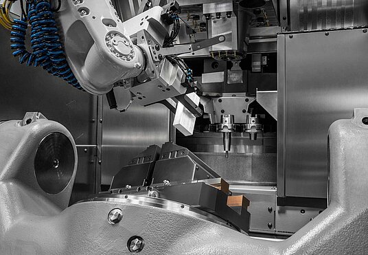
For Wener, the secret of success is in the machine's dual capabilities: "While the material is being milled, it can also be swivelled. This gives us a great advantage compared with conventional turning machines." The simultaneous swivelling capability means that shorter and therefore more rigid tools can be used. On top of that, it is also possible to machine complex contours with just one tool. "So our users require fewer tools, and they can be standard tools. This enables them to make significant savings on investments," explains Wener.
Of equal importance are the aspects of precision, stability and long-term accuracy. An engine series can span a large period of time, up to 20 years. Manufacturers expect our machines to match this with equally long precision and reliability specifications – down to the last part to be machined," says Wener. "Considering how difficult some machining materials such as Inconel or custom-designed high-temperature resistant materials can be to mill, as well as how complex the 5-axis geometries worked on our machines sometimes are, this makes for some very demanding challenges." And although replacement part availability is important in all sectors, the requirements regarding machine uniformity are especially strict in the aerospace industry. Wener explains: "Even where a project extends over several years, we are able to give our customers a guarantee that all machines that we construct and supply in a given space of time are identical – irrespective of any software updates or hardware system modifications that may have been introduced." This is where Hermle's standardization concept scores points against special machine designs.
One machine, two techniques
Hermle currently supplies three High-Performance Line machines as MT variants: the C 42 U, C 52 U and the C 62 U. These allow customers to perform simultaneous rotational machining on workpieces up to a diameter of 1200 millimetres and a height of 900 millimetres. The following maximum weights must not be exceeded: 700 kg (C 42 U MT), 1000 kg (C 52 U MT) and 1500 kg (C 62 U MT). This restriction results from the enormous rotational momentum involved. The rigid construction that is essential for rotational machining is standard on Hermle machines anyway. However, one development that has certainly been significantly influenced by the aerospace applications is the hydraulic bearing preloading for the spindle. "The spindle is the weakest link in the entire system. That is why we have developed a rigidity system that responds to the rotational speed," explains Wener. The bearing load is automatically adjusted by the control system: At lower rotational speeds, the spindle system is made significantly more rigid – i.e. when the machine has to process materials that are difficult to handle. In addition, the bearing assemblies are given extra hydraulic support at low speeds. As the speed increases, the hydraulic pressure is reduced, until the bearing preloading is determined by the spring assembly alone.


